7 Tips for Choosing Aluminum Contact Wire
Aluminum Contact Wire can look straightforward on a product sheet, yet its performance depends on more than the alloy name. A railway line, industrial current collector, and overhead power system place different demands on the conductor. The right choice balances electrical conductivity, tensile strength, weight, wear resistance, and compatibility with existing equipment. Small details matter.
A useful evaluation starts with the actual operating conditions. Consider current load, span length, tension, weather exposure, and how the wire will be joined or maintained. A lightweight conductor may reduce structural load, but it still needs adequate mechanical strength and reliable electrical contact. Surface finish matters too; roughness, oxidation, or uneven dimensions can affect installation and service performance. Trade-offs remain.
Supplier documentation can help separate measurable facts from broad marketing claims. Check alloy and temper specifications, dimensional tolerances, test reports, and traceability records. Compare these details with project requirements, and ask a qualified engineer or purchaser to review any uncertain specifications. No single wire suits every route. Even a product with strong laboratory results may behave differently under local loads, vibration, temperature changes, and maintenance practices. The seven tips that follow offer a practical framework for comparing options, spotting missing information, and making a more defensible selection. Some choices will still require judgment. That is worth acknowledging.
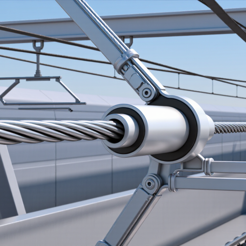
Define the Application and Operating Conditions
7 Tips for Choosing Aluminum Contact Wire
Define the Application and Operating Conditions
Start with the job the wire must do. A high-speed railway, an industrial trolley line, and a fixed power connection face different loads. Record the current profile, voltage, span length, support spacing, and expected mechanical tension. Include train speed and pantograph contact behavior where relevant. Small details matter.
The Aluminum Association’s Aluminum Standards and Data handbook gives a density near 2.70 g/cm³ for aluminum. Its electrical conductivity varies with alloy and temper; electrical-grade aluminum is commonly around 61% IACS. These are reference values, not finished-wire guarantees. I would not treat either figure as a design answer. Ask for certified data on the proposed wire, including resistance, tensile strength, and allowable operating temperature.
Then describe the site itself. Note ambient temperature ranges, direct sun, wind, ice exposure, dust, and corrosive moisture. These conditions affect thermal performance, sag, fatigue, and maintenance needs. Check how joints and fittings handle aluminum’s oxide layer, and confirm compatibility with the existing system. A desk estimate can miss local hot spots. Field measurements are better, especially where loads vary through the day. If operating records are incomplete, state that uncertainty before selecting a conductor; assumptions should be reviewed, not quietly treated as facts.
7 Tips for Choosing Aluminum Contact Wire - Define the Application and Operating Conditions
| Tip | Application or Condition | Information to Define | Why It Matters for Selection |
|---|---|---|---|
| 1. Identify the service | Urban tram, metro, suburban rail, or mainline railway | Route type, vehicle fleet, operating schedule, and whether the wire is for a new installation or a replacement | Traffic density, vehicle current demand, and maintenance access differ between transit and mainline systems. |
| 2. Confirm the electrical system | Common railway systems include 750 V DC, 1.5 kV DC, 3 kV DC, and 15 kV or 25 kV AC | Nominal voltage, permitted voltage range, traction load profile, and the applicable infrastructure standard | Voltage and current requirements influence the contact-line design. The complete system—not the wire alone—must meet electrical and safety requirements. |
| 3. Record operating speed | Low-speed urban routes through to high-speed rail corridors | Maximum and typical train speed, pantograph type, and the required contact-wire geometry | Higher speeds make dynamic interaction between the pantograph and contact line increasingly important. Confirm suitability against the line design and relevant standards. |
| 4. Describe the environment | Coastal, industrial, cold, hot, humid, or heavily polluted locations | Site temperature range, humidity, airborne salt or contaminants, and exposure to water or chemicals | Environmental exposure can affect corrosion, wear, inspection intervals, and the choice of compatible materials and fittings. |
| 5. Check mechanical loading | Open track, tunnels, bridges, and areas exposed to wind or ice | Span arrangement, support spacing, tensioning method, expected wind or ice loading, and available installation clearance | Mechanical loads and layout affect sag, clearances, fatigue, and the required strength of the contact-line assembly. |
| 6. Assess current and temperature conditions | Routes with frequent acceleration, steep gradients, or sustained heavy traffic | Peak and continuous current, train headway, ambient temperature, and cooling conditions | Electrical heating depends on current, conductor properties, and heat dissipation. Confirm allowable operating temperature and ampacity using the project design method. |
| 7. Define maintenance and compatibility needs | Existing overhead contact-line systems or locations with limited access for maintenance | Existing wire profile and dimensions, connector and clamp compatibility, inspection access, and replacement strategy | Matching the existing system can reduce installation changes and help maintain consistent pantograph contact. Verify dimensions and material compatibility before ordering. |
Note: The voltage levels shown are examples of commonly used railway systems, not product specifications. Final wire selection, ratings, dimensions, and installation details should be confirmed against the project requirements and applicable standards.